| |||
ISDN History
ISDN (Integrated Services Digital Network) is a digital telephone standard designed to replace analogue connections by utilising ordinary copper wires that are used in standard analogue telephone systems. It started as a recommendation within the ITU's (International Telecommunication Union) Red Book in 1984, although prior to 1992, the ITU was known as the CCITT (International Telegraph and Telephone Consultative Committee). The ITU is responsible for developing recommendations on International Standards within the industry.
ISDN was developed to provide digital transmission of both voice and data resulting in better quality and speeds over that of PSTN (Public Switched Telephone Network) systems.
Getting to Know the Digital ProtocolThere are two types of IDSN Channels.
• The B-Channel – This is known as the Bearer (“B”) channel which is a 64Kbps channel used for voice, video, data or multimedia transfer. These can be aggregated together to get higher bandwidth utilisation.
• The D-Channel – This is known as the Delta (“D”) channel which can be either 16Kbps or 64Kbps used primarily for the signalling between the switching equipment. Some say that this adds to the security of ISDN because the controlling and data channels are separate.
N.B. Digital Signal 0 (DS0) is a basic digital signalling rate of 64Kbits which may be used to describe a single Bearer channel.
BRI (Basic Rate Interface)
Can also be known as BA (Basic Access), this operates a single 16Kbps D channel and two 64Kbps B channels. Although it isn't usually pointed out, the BRI total speed is 192Kbps, this is because you have an additional 48Kbps overhead for framing and synchronisation on the D channel. (64 * 2) + (16 + 48) = (128 + 64) = 192Kbps.
PRI (Primary Rate Interface)
Can also be known as PA (Primary Access), this can operate in two different modes depending on your geographic location. For European locations, PRI is made up of 30 x 64Kbps B channels and a single 64Kbps D channel which gives a total of 2.048Mbps which is also known as an E1 line (or DS1). For American and Japanese locations, PRI is made up of 23 x 64Kbps B channels and a single 64Kbps D channel which give a total of 1.544Mbpts which is also known as a T1 line (or DS1). Framing and Synchronisation is at 8Kbps for T1 or 64Kbps for E1. T1 PRI is commonly referred to as “23B+D” and for E1 PRI is commonly referred to as “30B+D”.
N.B. E1 PRI actually has 32 channels which are comprised of 30 x B Channels, 1 x D Channel and 1 Synchronisation Channel.
Digital Signal Levels (DSx)
Digital Signal X is used to describe standard digital transmission rates or levels based on DS0 which is defined as a transmission rate of 64Kbps. This is the rate for one telephone voice channel. This is based on the ANSI T1.107 guidelines and the ITU guideline does differ slightly. The following tables show you the DS level and the corresponding speed and T/E classification.
T Carrier
Digital Signal Level | T Speed | T Classification | Channels |
DS0 | 64 Kbps | N/A | 1 |
DS1 | 1.544 Mbps | T1 | 24 |
DS2 | 6.312 Mbps | T2 | 96 |
DS3 | 44.368 Mbps | T3 | 672 |
E Carrier
Digital Signal Level | E Speed | E Classification | Channels |
DS0 | 64 Kbps | N/A | 1 |
DS1 | 2.048 Mbps | E1 | 32 |
DS2 | 8.448 Mbps | E2 | 128 |
DS3 | 34.368 Mbps | E3 | 512 |
DS4 | 139.264 Mbps | E4 | 2048 |
DS5 | 565.148 Mbps | E5 | 8192 |
As you can see from the tables, you can see where the guidelines differ slightly. In fact, depending on what sources you read, these tables may differ slightly.
Point-to-Point Protocol (PPP)
ISDN will typically use the Point-to-Point (PPP) Tunnelling protocol as its basis of transmitting packets over the ISDN circuit. The IP Packets are encapsulated into the PPP packets before the traffic is sent.
PPP provides link specific control functions via Link Control Protocol (LCP) such as Link Configuration, Link Quality Testing & Address Negotiation. LCP provides more advanced features, such as Multilink, Header Compression, Callback, Scripting, Demand Dialing, Filtering, Tunnelling and Server Routing. There are also authentication mechanisms that can help to ensure that the ISDN connection that is established is from a trusted source. Authentication is optional which can be performed by the use of PAP, CHAP & EAP (although EAP is not used in ISDN implementations, EAP is however a valid authentication method of PPP).
PAP – Password Authentication Protocol is not strong since the password is sent in clear text. PAP occurs during the LCP phase of the PPP connection.
CHAP – Challenge Handshake Authentication Protocol, is much stronger then PAP and is much more widely used. It uses a Challenge/Response security mechanism which uses a one way Hash Function to ensure that the passwords are not sent over the link. The password is Hashed and sent over the link, the other side of the link then performs the same hashing function on the password that they have configured then check to ensure that the two hash values are the same. This can also provide protection against playback.
EAP – Extensible Authentication Protocol provides the ability to use multiple authentication protocols such as static passwords, CHAP, Token Cards, Biometrics, etc... As you can imagine, since CHAP is available on its own and ISDN cannot really work with Token Cards or Biometrics it isn't used in ISDN implementations.
ISDN Layers, Protocols & Components
Introduction
ISDN uses circuit-switching to establish a physical permanent point-to-point connection from the source to the destination. ISDN has standards defined by the ITU that encompass the OSI bottom three layers of which are Physical, Data Link and Network, see Table 1 below.
At the physical layer the ITU has defined the user network interface standard as I.430 for Basic Rate Access and I.431 for Primary Rate Access; please see the ITU-T I.414 “Overview of Recommendations on Layer 1 for ISDN and B-ISDN customer accesses” document on the ITU's website. ANSI has defined the user network interface standard as T1.601. As already stated above, the physical layer uses the normal telephone cabling as its physical cabling structure.
The ISDN B channels will typically utilise a Point-to-Point protocol such as HDLC (High-Level Data Link Control) or PPP frames at Layer 2 however you can sometimes see other encapsulation such as Frame relay. As you would expect, at layer 3 you typically see IP packets. ISDN operates in Full-Duplex which means that traffic can be received and transmitted at the same time.
The ISDN D channel will utilise different signalling protocols at Layer 3 and Layer 2 of the OSI Model. Typically at Layer 2, LAP-D (Link Access Procedure – D Channel) is the Q.921 signalling used and DSS1 (Digital Subscriber Signalling System No.1) is the Q.931 signalling that is used at Layer 3. It is easy to remember which one is used at which layer by simply remembering that the middle number corresponds to the layer it operates at.
Table 1
OSI Layer | B Channel | D Channel |
3 | IP | DSS1 (Q.931) |
2 | HDLC/PPP | LAP-D (Q.921) |
1 | I.430/I.431 or ANSI T1.601 | |
The Different ISDN Components
As part of the ISDN Standards, there are several types devices that are used to connect to the ISDN network which are known as Terminal Equipments (TE) and also Network Termination (NT) equipment. You also have Reference Points which are used to define the connections between the various equipment that is used within the ISDN network.
Terminal Equipment and Network Termination Definitions;
• Terminal Equipment Type 1 (TE1) are devices that can plug directly into an ISDN Network and understands the ISDN standards
• Terminal Equipment Type 2 (TE2) are devices that predate the official ISDN standards and require the use of a terminal adapter (TA) to facilitate plugging into the ISDN Network. These can simply be routers that only have a serial interface on them and not an ISDN WIC. The terminal adapter can plug into the serial interface and allow the router to be used to connect to the ISDN network. Another example would be a Personal Computer (PC).
• Network Termination 1 (NT1) is typically a customer's device that is used to implement the physical layer specification into the ISDN Network (or the NT2 device). This is the U Reference point that connects through to the telco. This operates at Layer 1 of the OSI Model.
• Network Termination 2 (NT2) is typically the telco's device (it's very rare to see this at the customers site) that is used to terminate from the customers NT1 device before traffic hits the ISDN network. This operates at Layer 2 & 3 of the OSI Model and is an intelligent device performing the switching.
• Terminal Adapter (TA) is used to convert TE2 device signalling into signalling that is used by the ISDN switch.
Different ISDN Reference Points
• R – This reference point is used to specify the point between the TE2 device and the TA device.
• S – This reference point is used to specify the point between the customers router and the NT2 device.
• T – This reference point is used to specify the point between the NT1 device and the NT2 device S and T reference points can perform the same functions therefore they are sometimes referred to as an S/T reference point. When we are plugging into the S/T reference point location, the function of the NT2 is redundant since it's built in.
• U – This reference point is used to specify the point between the NT1 device and the telco's termination equipment in the ISDN carrier network, apart from in North America where the NT1 function isn't provided by the carrier network.
Cisco Router Options
With Modular Cisco Routers, they come with slots where you can plug in various cards different types of WAN Interface Cards (WIC). Cisco provide 2 different types of WICs for ISDN support. These different cards provide either a ISDN WIC with the S/T reference points which plug into an NT1 device or an ISDN WIC with a U reference point which has the NT1 built into the WIC itself.
Which WIC is required depends on your location and the telco that provides the ISDN circuit. For example, in North America , they use a two-wire connection which is a WIC card with the U reference point, having the NT1 built into it.
More information regarding the configuration of Cisco routers and ISDN confguration can be found in our Basic ISDN Configuration article.
Understanding MPLS IP VPNs, Security Attacks and VPN Encryption
What Are MPLS Networks?
Multi-Protocol Label Switching (MPLS) networks are the next-generation of networks designed to allow customers create end-to-end circuits across any type of transport medium using any available WAN technology. Until recent years, customers with the need to connect remote offices in locations across the country were restricted to the limited WAN options service providers offered, usually Frame Relay or T1/E1 dedicated links. The problem with these WAN technologies is that they are usually very expensive and complex to manage, but also not very flexible, making them a headache for both the end customer and service provider. Worst of all, as the distance between the customer’s end points increased, so did the monthly bill.
How MPLS Networks Work
MPLS works by tagging the traffic entering the MPLS network. An identifier (label) is used to help distinguish the Label Switched Path (LSP) to be used to route the packet to its correct destination. Once the best LSP is identified by the router, the packet is forwarded to the next-hop router. A different label is used for every hop and the label is selected by the router (or switch) that is performing the forwarding operation.
Take for example the below diagram. It shows a simple MPLS network example where the central server is sending packets to two remote hosts.
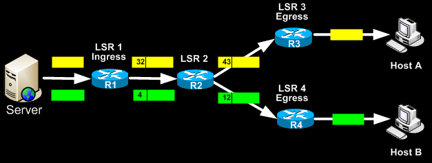
The Ingress router (LSR1) accepts the packets from the server and selects the best LSP based on their destination IP Address. It then selects an initial label (local significance) for each packet and then forwards the packets using MPLS. When Router2 receives the packets, it uses these labels to identify the LSPs from which it selects the next hops (R3 & R4) and labels (43 & 12). At the end of the path, the egress routers (R3 & R4) remove the final label and send the packet out to the local network.
One of the great advantages offered by MPLS networks is the built-in Quality of Service mechanisms. MPLS service providers usually offer an end-to-end QoS policy to ensure their customer MPLS networks have guaranteed QoS through the MPLS network backbone. This allows delay-sensitive services such as VoIP to be implemented with guaranteed bandwidth between the endpoints.
There really is no limitation to the type of services that can be run over a MPLS network. The QoS mechanisms and prioritisation services, allow the quick and effective forwarding of traffic between customer endpoints.
MPLS VPN Basics
MPLS VPNs combine the power of MPLS and the Border Gateway Protocol (BGP) routing protocol. MPLS is used to forward packets over the provider’s network backbone and BGP is used for distributing routes over the backbone.
A MPLS VPN is compromised of the following equipment:
- Customer Edge (CE) routers. These are placed at the customer site and are usually owned by the customer. Some service providers also supply the CE equipment for a small rental fee.
- Provider Edge (PE) routers. These are the provider’s edge routers to which the CE routers connect to. The PE routers are always owned by the service provider
- Provider (P) routers. These routers are commonly referred to as ‘transit routers’ and are located in the service provider’s core network
Routing information is passed from the Customer Edge router to the Provider Edge router using either a routing protocol such as BGP or static routes. The Provider Edge router keeps a per-site forwarding table also known as ‘VPN Routing and Forwarding tables’ or VRFs. At the Provider Edge router, each VRF serves a particular interface (or set of interfaces) that belongs to each individual VPN. Each Provider Edge router is configured by the service provider with its own VRF that is unique. Routers within the MPLS VPN network do not share VRF information directly.
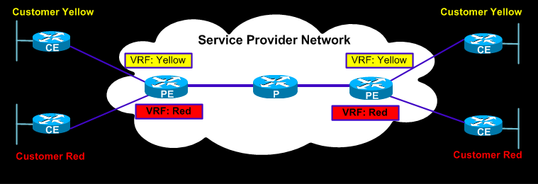 The above diagram illustrates a typical MPLS VPN network where VRFs are unique for each VPN connected to a particular Provider Edge router
What’s important about MPLS VPN services is that there is no boundary to the type of WAN technology used. This means you can run MPLS over ATM (Also known as MPLS IP VPN over ADSL), leased lines, Satellite links, wireless links and much more. This flexibility makes MPLS networks a preferred method of connecting offices between each other. The ISP provides the interface to which the local network is connected (usually a router with a LAN interface) and all that’s required is to connect the provided interface to the local network, set the necessary equipment to use the new gateway (MPLS CE router) and everything magically works!
Internet access is also possible through the MPLS IP VPN service where the service provider (ISP) typically announces the routes of customers that require direct access to the Internet, without affecting the performance of their intrasite VPN links. For example, this means that it’s possible to have a 1024Kbps MPLS link to your ISP which splits to a 512Kbps MPLS IP VPN link to your remote site and a further 512Kbps link to the Internet. The ISP completely separates these two virtual links, even though they run through the same interface. The link providing Internet access makes use of Network Address Translation (NAT) to translate the private network address space from the customer’s network. In this case, the customer reveals no more information to the Internet than it would with any normal connection to the Internet.
Resistance to Attacks
There is a growing concern as to how secure MPLS IP VPNs really are and how they can be protected from Internet attacks. Fortunately, the answer is pretty straight forward and doesn’t require a lot of technical analysis to see why.
In pure MPLS IP VPN environments without Internet access, where the network is used to connect different sites, the core network and customer address space is concealed 100%. This means that no information is revealed to third parties or the Internet. With no information revealed, hackers are unable to obtain access to critical information such as router IP addresses in order to perform Denial of Service (DoS) attacks and bring down the network.
In addition, service providers prevent their routers from being reachable via the Internet by using well-known techniques such as packet filtering, applying access control lists (ACLs) to limit access only to the ports of the routing protocol (e.g BGP) from specific areas within their network.
In an environment where Internet access is provided to the customer via the MPLS link, ISP’s use similar mechanisms to lock down their Customer Edge routers that provide access to the Internet. In addition, the routing protocols used by the ISP have built-in mechanisms that are usually enabled and increase the security level even more. A few examples are the configuration of the MD5 authentication for routing protocols (BGP, OSPF e.t.c), configuration of maximum number of routes accepted per Virtual Routing and Forwarding instance (VRF) and a few more.
MPLS IP VPN Encryption
While MPLS IP VPN provides a scalable model in which customers can securely connect remote sites between each other, there have been quite a few discussions about the encryption services offered by service providers for these circuits.
The fact is that MPLS IP VPN usually do not offer any encryption services. The MPLS VPN architecture makes it pretty impossible to hack into the MPLS circuits and expose the internal network(s) and routes, unless a major bug or configuration flaw exists somewhere in the provider’s network.
Encryption of the MPLS VPN is performed using IPSec, which essentially is a suite of protocols designed to provide a secure IP based pathway between two or more endpoints. You can read more on IPSecurity on Firewall.cx’s dedicated IPSecurity article.
Below are two examples of IPSec encryption between two sites connected via MPLS VPN:
CE-CE IPSec
In this example, the IPSec is used between the CE’s on each end, therefore the entire path between the CEs is protected. This setup offers the best possible protection against possible hacking attempts. Packets enter the CE router and are immediately encrypted. When packets are decrypted on the other end, they are located directly at the customers LAN network.
CE-CE IPSec offers true protection against the following threats:
- Anti-Replay. Replay of legitimate packets that have been recorded previously
- Change of packets that are in transit between the sites
- Eavesdropping anywhere between the CEs, PE or P routers.
PE-PE IPSec
This method is by far less secure than the previous one examined. IPSec encryption occurs from the PE routers onwards, leaving the rest of the network unencrypted and therefore not providing true VPN security.
PE-PE IPSec offers true protection against the following threats:
- Eavesdropping between the PEs or P routers
- Generally, point-to-point connections are easy to manage but when the scenario gets more complex with multiple endpoints. IPSec tunnels do have a considerable administrative overhead that shouldn’t be taken lightly. For example, maintaining an IPSec topology between 5 sites requires the configuration of multiple Crypto IPSec tunnels on each router located at every site. Any changes made to one router (e.g internal routes or LAN IP Addressing) requires the reconfiguration of all other routers so that the IPSec tunnels continue working correctly.
ATM (DSL) IP VPN Networks
There is no doubt about the flexibility, security and scalability of MPLS IP VPN networks. Thousands of Enterprise customers are moving from the old and expensive leased-line solutions to the much cheaper MPLS VPN alternative for all the previously mentioned reasons.
While MPLS networks have gained popularity during these last years, ATM IP VPN networks (referred to as ‘DSL IP VPNs’ from now on) are starting to gain considerable attention to the point where they are offered as an alternative to MPLS VPNs!
DSL IP VPNs rely on the customer’s direct Internet connection to create a VPN IPSec tunnel between two endpoints. A typical scenario is a customer with two sites that require connectivity between each other. Both sides are equipped with a fast DSL connection using static IP addresses. The configuration is performed on the Customer Edge routers to create an IPSec tunnel between the two sites.
In most cases, the end result is pretty much the same as any MPLS network, but one could argue about the security offered by such a setup, especially when the CE routers are directly connected to the Internet. Tests performed by large vendors such as Cisco Systems have proven that the security provided in these solutions is directly comparable with that of an MPLS VPN, considering of course proper configuration of the CE routers has been performed.
The advantages offered by DSL IP VPNs is that the costs are extremely low and equal to that of each side’s connection to the Internet. Companies seeking to cut costs on data telecommunication services are already moving to this new trend which has become extremely popular in Europe and Asia.
Despite the advantages, one must keep in mind the following disadvantages DSL IP VPNs have:
- In order to obtain high VPN speeds between sites, both CE routers must connect to the same ISP so they run on a common backbone.
- CE Routers are directly exposed to the Internet and therefore are vulnerable to DoS attacks
- QoS is not usually guaranteed. Because packets are routed through the ISP backbone using the same path and priority normal Internet users have, there is no QoS guarantee
- Limited scalability. Site to Site DSL IP VPN is great for up to a few sites. Depending on the amount of users located on each site, more than one DSL connection might be required per site
In our next article we will examine DSL IP VPNs in much greater depth, including DSL IP VPN requirements, their security encryption mechanisms, QoS methods, backup methods, and much more.
No comments:
Post a Comment