Site-to-Site IPSec VPN Tunnels are used to allow the secure transmission of data, voice and video between two sites (e.g offices or branches). The VPN tunnel is created over the Internet public network and encrypted using a number of advanced encryption algorithms to provide confidentiality of the data transmitted between the two sites. This article will show how to setup and configure two Cisco routers to create a permanent secure site-to-site VPN tunnel over the Internet, using the IP Security (IPSec) protocol. ISAKMP (Internet Security Association and Key Management Protocol) and IPSec are essential to building and encrypting the VPN tunnel. ISAKMP, also called IKE (Internet Key Exchange), is the negotiation protocol that allows two hosts to agree on how to build an IPsec security association. ISAKMP negotiation consists of two phases: Phase 1 and Phase 2. Phase 1 creates the first tunnel, which protects later ISAKMP negotiation messages. Phase 2 creates the tunnel that protects data. IPSec then comes into play to encrypt the data using encryption algorithms and provides authentication, encryption and anti-replay services. IPSec VPN RequirementsTo help make this an easy-to-follow exercise, we have split it into two steps that are required to get the Site-to-Site IPSec VPN Tunnel to work. These steps are: (1) Configure ISAKMP (ISAKMP Phase 1) (2) Configure IPSec (ISAKMP Phase 2, ACLs, Crypto MAP) Our example setup is between two branches of a small company, these are Site 1 and Site 2. Both the branch routers connect to the Internet and have a static IP Address assigned by their ISP as shown on the diagram: 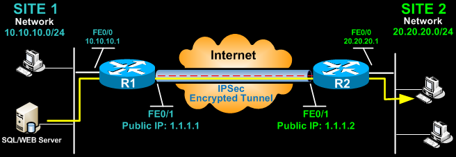 Site 1 is configured with an internal network of 10.10.10.0/24, while Site 2 is configured with network 20.20.20.0/24. The goal is to securely connect both LAN networks and allow full communication between them, without any restrictions. Configure ISAKMP (IKE) - (ISAKMP Phase 1)IKE exists only to establish SAs (Security Association) for IPsec. Before it can do this, IKE must negotiate an SA (an ISAKMP SA) relationship with the peer. To begin, we’ll start working on the Site 1 router (R1). First step is to configure an ISAKMP Phase 1 policy: R1(config)# crypto isakmp policy 1 R1(config-isakmp)# encr 3des R1(config-isakmp)# hash md5 R1(config-isakmp)# authentication pre-share R1(config-isakmp)# group 2 R1(config-isakmp)# lifetime 86400 The above commands define the following (in listed order): 3DES - The encryption method to be used for Phase 1. MD5 - The hashing algorithm Pre-share - Use Pre-shared key as the authentication method Group 2 - Diffie-Hellman group to be used 86400 – Session key lifetime. Expressed in either kilobytes (after x-amount of traffic, change the key) or seconds. Value set is the default value. We should note that ISAKMP Phase 1 policy is defined globally. This means that if we have five different remote sites and configured five different ISAKMP Phase 1 policies (one for each remote router), when our router tries to negotiate a VPN tunnel with each site it will send all five policies and use the first match that is accepted by both ends. Next we are going to define a pre shared key for authentication with our peer (R2 router) by using the following command: R1(config)# crypto isakmp key firewallcx address 1.1.1.2 The peer’s pre shared key is set to firewallcx and its public IP Address is 1.1.1.2. Every time R1 tries to establish a VPN tunnel with R2 (1.1.1.2), this pre shared key will be used. Configure IPSecTo configure IPSec we need to setup the following in order: - Create extended ACL - Create IPSec Transform - Create Crypto Map - Apply crypto map to the public interfaceLet us examine each of the above steps. Creating Extended ACLNext step is to create an access-list and define the traffic we would like the router to pass through the VPN tunnel. In this example, it would be traffic from one network to the other, 10.10.10.0/24 to 20.20.20.0/24. Access-lists that define VPN traffic are sometimes calledcrypto access-list or interesting traffic access-list. R1(config)# ip access-list extended VPN-TRAFFIC R1(config-ext-nacl)# permit ip 10.10.10.0 0.0.0.255 20.20.20.0 0.0.0.255 Create IPSec Transform (ISAKMP Phase 2 policy)Next step is to create the transform set used to protect our data. We’ve named this TS: R1(config)# crypto ipsec transform-set TS esp-3des esp-md5-hmac The above command defines the following: - ESP-3DES - Encryption method - MD5 - Hashing algorithm Create Crypto MapThe Crypto map is the last step of our setup and connects the previously defined ISAKMP and IPSec configuration together: R1(config)# crypto map CMAP 10 ipsec-isakmp We’ve named our crypto map CMAP. The ipsec-isakmp tag tells the router that this crypto map is an IPsec crypto map. Although there is only one peer declared in this crypto map (1.1.1.2), it is possible to have multiple peers within a given crypto map.R1(config-crypto-map)# set peer 1.1.1.2 R1(config-crypto-map)# set transform-set TS R1(config-crypto-map)# match address VPN-TRAFFIC Apply Crypto Map to the Public InterfaceThe final step is to apply the crypto map to the outgoing interface of the router. Here, the outgoing interface is FastEthernet 0/1. R1(config)# interface FastEthernet0/1 R1(config- if)# crypto map CMAP Note that you can assign only one crypto map to an interface. As soon as we apply crypto map on the interface, we receive a message from the router that confirms isakmp is on: “ISAKMP is ON”. At this point, we have completed the IPSec VPN configuration on the Site 1 router. We now move to the Site 2 router to complete the VPN configuration. The settings for Router 2 are identical, with the only difference being the peer IP Addresses and access lists: R2(config)# crypto isakmp policy 1 R2(config-isakmp)# encr 3des R2(config-isakmp)# hash md5 R2(config-isakmp)# authentication pre-share R2(config-isakmp)# group 2 R2(config-isakmp)# lifetime 86400 R2(config)# crypto isakmp key firewallcx address 1.1.1.1 R2(config)# ip access-list extended VPN-TRAFFIC R2(config-ext-nacl)# permit ip 20.20.20.0 0.0.0.255 10.10.10.0 0.0.0.255 R2(config)# crypto ipsec transform-set TS esp-3des esp-md5-hmac R2(config)# crypto map CMAP 10 ipsec-isakmp R2(config-crypto-map)# set peer 1.1.1.1 R2(config-crypto-map)# set transform-set TS R2(config-crypto-map)# match address VPN-TRAFFIC R2(config)# interface FastEthernet0/1 R2(config- if)# crypto map CMAP Bringing Up and Verifying the VPN TunnelAt this point, we’ve completed our configuration and the VPN Tunnel is ready to be brought up. To initiate the VPN Tunnel, we need to force one packet to traverse the VPN and this can be achieved by pinging from one router to another: R1# ping 20.20.20.1 source fastethernet0/0 Type escape sequence to abort. Sending 5, 100-byte ICMP Echos to 20.20.20.1, timeout is 2 seconds: Packet sent with a source address of 10.10.10.1 .!!!! Success rate is 80 percent (4/5), round-trip min/avg/max = 44/47/48 ms The first ping received a timeout, but the rest received a reply, as expected. The time required to bring up the VPN Tunnel is sometimes slightly more than 2 seconds, causing the first ping to timeout. To verify the VPN Tunnel, use the show crypto session command: R1# show crypto session Crypto session current status Interface: FastEthernet0/1 Session status: UP-ACTIVE Peer: 1.1.1.2 port 500 IKE SA: local 1.1.1.1/500 remote 1.1.1.2/500 Active IPSEC FLOW: permit ip 10.10.10.0/255.255.255.0 20.20.20.0/255.255.255.0 Active SAs: 2, origin: crypto map Network Address Translation (NAT) and IPSec VPN TunnelsNetwork Address Translation (NAT) is probably configured to provide Internet access to internal hosts. When configuring a Site-to-Site VPN tunnel, it is imperative to instruct the router not to perform NAT (deny NAT) on packets destined to the remote VPN network. This is easily done by inserting a deny statement at the beginning of the NAT access lists as shown below: For Site 1’s router: R1(config)# ip nat inside source list 100 interface fastethernet0/1 overload R1(config)# access-list 100 remark -=[Define NAT Service]=- R1(config)# access-list 100 deny ip 10.10.10.0 0.0.0.255 20.20.20.0 0.0.0.255 R1(config)# access-list 100 permit ip 10.10.10.0 0.0.0.255 any R1(config)# access-list 100 remark And Site 2’s router: R2(config)# ip nat inside source list 100 interface fastethernet0/1 overload R2(config)# access-list 100 remark -=[Define NAT Service]=- R2(config)# access-list 100 deny ip 20.20.20.0 0.0.0.255 10.10.10.0 0.0.0.255 R2(config)# access-list 100 permit ip 20.20.20.0 0.0.0.255 any R2(config)# access-list 100 remark |
Establishing an Inter-company VPN connections (Extranet):
After reading this section you should be able to configure peering Cisco routers
using IPSecand understand the functionality of each command. All configuration
presented below is specific to Cisco Hardware running IOS 12.1 or higher.
However, it is important to note,“IPSec is standards-based, Cisco devices will be
able to interoperate with other IPSec-compliant networking devices…”
This allows for a lot of flexibility. All companies do not deploy the same networking
hardware in their environment, but as long as they are IPSec compliant,network
connectivity can be established via IPSec tunneling protocol.
When creating IPSec tunnels, the main goal is to protect data flows that
carry confidential or sensitive data over an untrusted or public network.
Therefore, before planning your IPSec tunnel implementation, you must
have a solid understanding of the traffic you want protected by IPSec
tunnels, and the sources and destinations of this traffic.
Below a fictional scenariohas been createdto adhere to the above criteria:
Alarge corporation(CorpHQ) has a business need to securely send/receive
confidential E-mail with athirdparty law firm (LawA). All forthcoming
configurationswill be based onself-created figure 2.

Crypto Policy
· Transform-set
· Access-list
· Defining your crypto map
Crypto Policy:
A cryptopolicy must be establishedidenticallyon bot h the corporate router and
the thirdparty corporation’s router including the pre-shared key. The only change
needed on the thirdparty’s peering router is CorpHQ’s tunnel terminating IP
address. Before configuring a crypto policy five parameters must be decided
upon by both ends of the VPN tunnel.If any of these parameters do not match,
the VPN tunnel cannot be established.
1. What encryptionwill be used? DES or 3DES
2. What Authentication? Pre-share, rsa-encr, rsa-sig
3. What Diffie-Hellman group? 1, 2 or 5
4. What Hash? SHA or MD5
5. What lifetime? Between 60-86400
To configure a policy use global configuration m ode as shown below:
CorpHQ(config)# crypto isakmp policy 60 # line 1
CorpHQ(config-isakmp)# encr 3des # line 2
CorpHQ(config-isakmp)# hash md5 # line 3
CorpHQ(config-isakmp)# authentication pre-share # line 4
CorpHQ(config-isakmp)# group 2 # line 5
CorpHQ(config-isakmp)# lifetime 3600 # line 6
CorpHQ(config)# crypto isakmp key [pre-shared key] address 216.86.145.1# line 7
Line 1 – Establish anISAKMP protection policy with priority. The highest priority
is 1 and the lowest priority 10,000.
This is the beginning of IKE negotiation process for IPSec.
Line 2 –Specifies Triple DES encryption used with this policy
Line 3 –Specifies MD5 as the hash algorithm
Line 4 – Specifies a pre-shared key must be used to apply the security policy
Line 5 –Specifieswhich Diffie-Hellman group will be applied.
Line 6 – Specifies when thecrypto policy’s security associationsexpireand must
be reestablished. 3600 seconds (1 hour) or 4,608,000 kilobytes (10MB per
second for one hour) is the default for a Cisco isakmp policy.
Line 7 – The pre-share key must be the same on each peer router. The crypto
isakmp shared key also specifies the terminating ends of the IPSEC tunnel.
Transform Set:
Transform sets are a combination of security protocols and algorithmsthat
protect the data flow across the internet. Specifically, the IPSec transform set
parameters is apre-established configuration on peering routersto form another
Security Association (SA).The SA configuration must match on each peering
router in order to successfully encrypt and authenticate from the sender and
decrypt and unauthenticated at the receiver.
Encryption and/orAuthentication must be selected out of the below choices:
ah-md5-hmac AH-HMAC-MD5 transform
ah-sha-hmac AH-HMAC-SHA transform
esp-3des ESP transform using 3DES(EDE) cipher (168 bits)
Any fake packets thatare sent to either end of an IPSec tunnel terminating point
will be discarded, because they will not pass the checksum verification. AH
provides three ofthefourfunctionalities for creating an IPSectunnel. Data
integrity, data authentication, and anti-replay services are all achieved through
AH, but not data confidentiality. With AH all data is sent in clear text and this is
why ESP is the preferred protocol used with IPSec tunnel creationfor Extranets.
Encapsulation Security Payload protocol ensures both data authentication and
confidentiality for IP data. ESP is able to guarantee both these services by
creating a new IP packet within an ESP header and trailer.An example of an
ESP packet is shown in figure 4.
Figure 4

(based on Mairs, 233)
Contained within the ESP header and trailer are the original IP Header, TCP
header and payload. These fields are encrypted using a manually specified
cryptographic algorithm.
This makes the original destination IP address, type of
data being sent (TCPheader), and the actual data being sent (payload)
unreadable while traversing the internet.
The authenticated portion of the ESP packet includes the ESP header and ESP
authentication. The ESP header contains twoparts (not shown in figure 4), the
Security Parameter Index (SPI) and the sequence number. “The SPI is an
arbitrary 32-bit value that, in combination with the destination IP address and
security protocol (ESP), uniquely identifies the Security Association for this
datagram.”
The SPI is the destination IP combined with a hash algorithm such
as MD5 or SHA. The second part is the sequence numberwhich implements a
counter with each packet. For example, when one packet is sent it is given a
number of 1, when the next packet is sent it is given a number of 2 and so on.
This function prevents replay attacks. If a fake packet is sent to the receiving
security gateway, it will be discarded, because it is not part of the increasing
number sequence. Lastly, ESP authentication trailer provides a checksum. If
any of the data within the ESP header ESP encrypted information has been
altered the packet will be discarded. Since the ESP protocol provides the highest
level of security and encrypt sdata acrossthe internet , itwill be used in theabove
fictional scenario.
CorpHQ(config)# crypto ipsec transform-set CorpHQ-vpnesp-3des esp-md5-hmac # line 1
CorpHQ(config)# mode (tunnel or transport) # line 2
Line 1 – ESP is selected because it provides both authentication and
confidentiality services. There are three parts to line one. “CorpHQ-vpn”is the
name of the Transform Set. Essentially, CorpHQ-vpn is the name of a security
association and the rest of the configuration establishes the rules of the SA.
“esp-3des” encapsulates and encrypts the IP Header, TCP Header and Payload
while traversing the internet. “esp-md5-hmac” authenticates the encrypted
packet with the destination IP address and anMD5 hashwhile traversing the
internet.Additionally, when NAT is introduced, ESP eliminatesconflicts between
NAT and AH’s checksum verification mechanism. ESP only performs integrity
checks on bits in the header that are not altered by NAT devices.
This will be covered in more detail in the Additional Securities section.
Line 2 - Tunnel mode is enabled by default on Cisco devices. “Tunnel mode is
used whenever either end of a security association is a gateway…..The
advantages of Tunnel mode are total protection of the encapsulated IP datagram
and ability to use private addresses.”
IPSec tunnel mode should be utilized
with extranet connectivity to a third party company. For reference, transport
mode can be used if less overhead processing is required by the security
gateway. Additionally, transport mode is often used when IPSec connectivity
between intranets needs to be established and every host in one intranet has
access to every host in the other.
Crypto Access List:
The crypto access list will specify which data traffic will passthrough the IPSec
tunnel .Crypto access lists aremore like security associationsthan traditional ip
access lists. “…the access lists used for IPSec are used only to determine which
traffic should be protected by IPSec, not which traffic should be blocked or
permitted…”.
CorpHQ and the same permit statement is mirrored on LawA then data is
authenticated, encrypted and passed across the IPSectunnel. As data reaches
the tunneling endpoint at LawA or vise versa, the crypto access l ist will discard
out any traffic that does not meet the permit criteria. Essentially, a crypto access
list applied to an interface filters both inbound and outbound traf fic. This provides
the strongest level of security.In addition, since we are configuring ipsec-isakmp
crypto maps, IPSecconnections will not be accepted unless they meet the
criteria of the permit statements.
Reference for below Access list:
CorpHQ interface IP address = 153.183.175.5
CorpHQtunnel terminating point = 178.175.99.78
LawAtunnel terminating point = 216.86.145.1
CorpHQMail-Relay = 197.175.99.75
LawAMail-Relay = 216.86.145.12
CorpHQ management subnet = 178.175.95.0
CorpHQ(config)# ip access-list extended LawA-intel # line 1
CorpHQ(config-ext-nacl)# permit icmp host 153.183.175.5 host 216.86.145.1 # line 2
CorpHQ(config-ext-nacl)# permit ip host 178.175.99.75 host 216.86.145.12# line 3
CorpHQ(config-ext-nacl)# permit ip host 178.175.99.78 host 216.86.145.12# line 4
CorpHQ(config-ext-nacl)# permit icmp 178.175.95.0 0.0.0.255 host 216.86.145.12# line 5
LawA would contain a mirrored Crypto Access-list.
LawA(config)# ip access-list extended(LawA-names-access-list)
LawA(config-ext-nacl)# permit icmp host 216.86.145.1 host 153.183.175.5
LawA(config-ext-nacl)# permit ip host 216.86.145.12 host 178.175.99.75
LawA(config-ext-nacl)# permit ip host 216.86.145.12 host 178.175.99.78
LawA(config-ext-nacl)# permit icmp216.86.145.12 host 178.175.95.0 0.0.0.255
Line 1 –Creating a named extended IP access list
Line 2 –Permits ICMP from the CorpHQ tunnel terminating interface to the LawA
tunnel terminating interface. This is used for management testing purposesin
orderto test layer 3 connectivity and latency across the internet. This allows
network personal to run extended pings from tunnel endpoints and prove IPSec
is functioning correctly.
Line 3 – Permits IP connectivity between the CorpHQ’s and LawA’s mail-relay
servers.
Line 4 –Permits IP connectivity from CorpHQ’s tunnel terminating end-point to
LawA’s mail-relay server.
Line 5 –Permits every host at CorpHQ on the 178.175.95.0 subnet to send ICMP
packets to LawA’s mail-relay server. This has been configured to allow network
management devices periodically send icmp requests to the mail server tomake
sure it is still connected to the network.
Crypto Maps:
A crypto map pulls all the pieces together required to create anIPSEC
connection. This includes thesecurity associations contained within the access-list and the transform set joinedwiththe peer address . These crypto maps will
be applied to interfaces through which IP traffic passing through the interface is
evaluatedagainst the applied crypto map set. If a crypto map entry sees
outbound IP traffic that should be protected and the crypto map specified the use
of IKE, a security association is negotiated with the remote peer according to the
security associationsin the crypto map. For IPSec to succeed between two
IPSec peers, both peers crypto map entries must contain compatible
configuration statements(SAs).
29
CorpHQ(config)#crypto map CorpHQ-vpn 60 ipsec-isakmp #line 1
CorpHQ(config-crypto-map)#set peer 216.86.145.1 #line 2
CorpHQ(config-crypto-map)#set transform-set CorpHQ-vpn #line 3
CorpHQ(config-crypto-map)#match address LawA-CorpHQ #line 4
Line 1 –Configuring the crypto map with a name CorpHQ-vpn with a sequence
number of 60.Ipsec-isakmp specifies that IKE will be used to establish the
IPSectunnel between peers. This command also places the user in crypto map
configuration mode allowing the user to specify the below parameters. NOTE:
This new crypto map will remain disabled until a peerand a valid access list have
been configured.
Line 2 – Sets the IPSectunnel’sremote terminating end.This tells CorpHQ
where it can forward protected traffic.
Line 3 – Configures the named transform-set to be used. The transform-set
contains Hash algorithm and Encryption method.Note: Several transform sets
can be configured under a single crypto map.
Line 4 –Applies the previously configured named Crypto access list to the crypto
map.The crypto access list describes what traffic should be protected.
Note: Optional parameters that specify additional SAs are configurable.
Applying an IPSec tunnel :
Once the crypto map has been established on both peering routers it is time to
apply the configuration to an interface.After this configuration, no additional
configuration coordination with LawA will need to be completed.
CorpHQ(config-if)# crypto map CorpHQ-vpn #line 1
Line 1 –Applies crypto map to an interface. All inbound traffic to the interface
will be processed against the crypto map. If it does not meetthe established
security associations of the crypto map the traffic will be dropped or, if specified
in the router configuration, routed elsewhere.
Recap:
At this point, there is now an IPSec tunnel created between LawA and CorpHQ
VPN concentrator routers. IPSec is providingencryption and authentication
which is protecting trusted data across an untrusted network (the internet). The
IP traffic destined from CorpHQ to LawA and vise versa must match the
established criteria of thecrypto map before it will be protected andallowed to
traverse the IPSec tunnel. In this case, data fromthe LawA’s mail-relay server
(216.86.145.12) and Concentrator terminating point (216.86.145.1) has access
intoCorpHQ’smail-relay server via the established IPSEC tunnel.
In many cases, corporations are content with this configuration and level of
security. However, the IP traffic from LawA’s mail-relay server to CorpHQ’s mail -relay server is unrestricted. Since CorpHQ does not own orcontrol LawA’s mail-relay server, CorpHQ cannot enforce company security policies and ensure
physical security of the box. Because of these two vulnerabilitiesCorpHQ has
the need to implement additional security parameters to ensure only e-mail traffic
is being passed between the two mail-relay servers.
Additional Security Parameters to be implemented with
IPSec:
Three security related parameters that can be configured on a Security Gateway
are extended IP Access Control Lists (ACLs), Network Address Translation
(NAT) and IP accounting.
Extend IP access list:
“IPSec implementations support machine-based certificates only, rather than
user certificates. As a result, any user with access to one of the endpoint
machines can use the tunnel.”
This results in the needfor a strict access list
with thirdparty companies. Without applying an access-list to CorpHQ’s router
interface (with an applied crypto map) a wide open door for LawA’s mail -relay
server has been created into CorpHQ’s mail-relay server. In theabove scenario,
there is only the need to pass e-mail traffic between tunnel endpoints. Any
Network traffic not meeting one of the below permit statements will be discarded
by the router oncetraversing the IPSec tunnelfrom LawA. The below extended
ACL configurationwill restrict thetunnel to SMTPnetwork traffic. For a complete
reference on extended IP access lists please reference Nancy Novato’s, July 5,
2001 GIAC practical.
32
Reference for below Access list:
CorpHQMail-Relay = 178.175.99.75
LawAMail-Relay = 216.86.145.12
CorpHQ(config)# ip access-list extended 101
CorpHQ(config-ext-nacl)#
access-list 101 permit tcp host 216.86.145.12 host 178.175.99.75 eq smtp
access-list 101 permit tcp host 216.86.145.12 eq smtp host 178.175.99.75 gt 1023
established
CorpHQ(config)# ip access-list extended 102
CorpHQ(config-ext-nacl)#
access-list 102 permit icmp host 178.175.99.35 host 216.86.145.1 2
access-list 102 permit tcp host 178.175.99.35 host 216.86.145.12 eq smtp
Network Address Translator(NAT)
NAT applies a defense in-depth methodology by adding another layer of security.
NAT is a router function defined in RFC 1631 and stemmed from the short term
need to conserve public IP address space. To accomplish this, private address
space was defined in RFC 1579.
Ranges are below:
10.0.0.0 -10.255.255.255
172.16.0.0 -172.31.255.255
192.168.0.0 -192.168.255.255
These ranges are not routable on the internet only within a private IP address
space, such as a company’s intranet. Unless a company plans on giving their
primary e-mail server a public IP address, NAT will need to be used with the
implementation of IPSec.
Caution must be taken when using NAT with IPSec tunnels. NATdevice can not
be placed in the middle of an IPSec tunnel when using AH because the source
and/or destination IP addresses are modified. This causes an AH packet to fail
the checksum verificationand the router believes the packet has been tampered
with, so the packet is discarded.
If you use Network Address Translation (NAT), you should configure static
NAT translations so that IPSec will work properly. In general, NAT
translation should occur before the router performs IPSec encapsulation;
in other words, IPSec should be working with global addresses.
34
In our given scenario, NAT is configure d for 2 reasons. The first reason is based
on functionality. CorpHQ does not want to route LawA’s public IP address into its
private network. In order to make an e-mail from LawA routable on CorpHQ’s
private network,NAT must readdress the traffic to be internally routable. The
second reason for implementing NAT (which is more of a side benefit) is
additional security. Combined with IPSec authentication and encryption NAT
provides aprivacy mechanism. Machines on the internet backbone cannot
monitor which hosts inside a company’s intranet are sending and receiving
packets.
35
CorpHQ(config)# ip nat outside source static 216.86.145.62 192.168.8.215 #line 1
Line 1 - In this case NAT replaces packets with the IP header of 206.86.145.62
with a new internal routable address of 192.168.8.225.
IP accounting:
After the above configuration isput intoplace,CorpHQ has done all they can at
the network layer to secure their Extrane t VPN connection with LawA. IP
accounting can be enabled on CorpHQ to monitor all network traffic and see if
any unwanted network traffic is traversing the IPSec tunnel terminating interface.
IP accounting output-packets configuration statement allows you view the source
and destination IP addresses traversing each ip accounting enabled interface.
Any unwanted network traffic can be detected.
CorpHQ(config-if)# ip accounting output-packets #line 1
Line 1 –This applies ip accounting to an interface. This w ill collect all of the outbound traffic for
an interface. Below, is a sample of ip accounting collected data from a cisco router.
Sourc e Destination Packets Bytes
173.185.42.166 192.168.8.224 60 5520
216.86.145.12 192.168.8.215480 28320
11.7.248.103 192.168.8.232 61 1708
Final Configuration:
CorpHQ# show interface fastehternet0/0
interface FastEthernet0/0
description ***CorpHQinternet ***
ip address 143.183.175.4 255.255.255.0
ip access -group 101 in #line 1
ip access -group 102 out #line 2
ip accounting output-packets #line 3
ip nat outside #line 4
duplex f ull
speed 100
crypto map CorpHQ-vpn #line 5
Line 1 –Applies access list 101 to all traffic that passes through interface
FastEthernet0/0 inbound
Line 2 –Applies access list 102 to all traffic that passes through interface
FastEthernet0/0 outbound
Line 3 –Records all traffic that passes through interface FastEthernet0/0
Line 4 –Applies NAT table for all outside public IP address.
Line 5 –Applies the Crypto map to the interface.
Conclusion:
The use of VPN technology continues to increase because of the tremendous
cost saving advantages to companies. There are many different types of VPN
technologies available, one being site-to-site VPN which is established between
IPSec compliant security gateways. These security gateways can be configured
with various security associations to protect private data across the internet.
Configuration of security gateways has been presented and explained to assist
an individual in establishing their own IPSec connection. The use of NAT, IP
extended access lists and IP accounting can be implemented to provide
additional security for an IPSec tunnel termination points.
I just want to thank you for sharing your information and your site or blog this is simple but nice Information I’ve ever seen i like it i learn something today. Best uk based vpn service
ReplyDelete