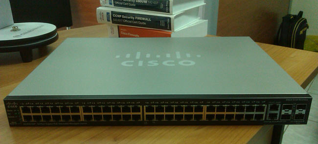
The SG500 series Cisco switches are the next step up from the already popular SG300 Layer-3 switches. Cisco introduced the SG Small Business series switches to compete against DELL’s and HP’s offerings and take the same share of the market.
Cisco saw the massive gap between its entry level Catalyst switches (2960S & 3560) and the competition, and decided to hit them as much as it could with the SG series switches.
The specifications on the newer SG 500 series switches are impressive: switching capacity starting from 28.8Gbps for the smallest 24-port SG500, up to 176Gbps for the largest models that include 10Gpbs uplinks, all with layer-3 switching, stacking and power efficiency capabilities!
Here are some highlights of the SG 500 Series:
- High-Power Power over Ethernet Plus (PoE+), providing up to 30 watts per port
- Full IPv6 Support
- Advanced Layer 3 Traffic Management (InterVLAN-Routing)
- Strong Security. Access Control Lists (ACLs), Voice VLAN, Guest VLAN and many more security features.
- Power Efficiency. Ability to automatic power shutoff ports not used, adjusting signal strength based on length of connecting cable etc.
- Expandability. Offering 1G and 1G/5G Ethernet expansion slots. 10G expansion slots for the 500X series.
- Limited lifetime warranty with next-business-day advanced replacement.
For our readers' convenience, we've made the following downloads available directly from Firewall.cx:
- Cisco SG500 Series Overview
- Cisco SG500 Series Datasheet
- Cisco SG500 Quick Start Guide
These are easily accessible in our SG500 Datasheet Download section.
Initial Setup of SG500-52P
Just like the SG200 & SG300 series, the SG500 can be configured by both Web and CLI interface. The Web interface is highly intuitive but does require some time to understand its layout and where to configure different aspects of the switch.
The CLI mode is similar to that of the Cisco IOS Catalyst switches but it has its own logic, something we believe Cisco did deliberately to ensure the SG series configuration experience is not ‘identical’ to the much more expensive and well known Catalyst switches.
We found that the best way to configure the switch was to use the CLI interface for specific functions such as setting up IP Addresses, creating and naming VLANs, setting default gateway, then using the web interface for configuring the trunk and access links, allowed VLANs etc. When we completed the configuration and performed a ‘show running-config’ in CLI mode, we then understood that some of the web configuration could have easily been done through CLI.
As with the SG200 & SG300 models, it is advised to always keep the firmware updated to the latest available version. Earlier SG300 firmware suffered from plenty of problems that could cause the switch to stop processing packets and required a reboot to restore functionality.
Hopefully, we won’t be experiencing the same problems with the SG500 firmware.
Before You Begin
Both SG300 and SG500 series switches are layer-3 capable, which means you can create multiple VLANs and route between them - a function called InterVLAN routing. For more information about InterVLAN routing, you can read our InterVLAN routing article.
Most people are not aware that when an SG300 or SG500 switch is powered up for the first time, it defaults to Layer-2 mode! In order to create multiple VLANs, assign IP Addresses and enable Layer-3 Switching, you must switch the SG300 & SG500 to router mode! When this is done all configuration is erased and the device is reset, losing any configuration performed.
It is therefore highly advisable to always switch to router mode before any configuration is performed on the switch!
Switching to ‘Router’ Mode – Enabling Layer-3 Switching
To switch to router mode, connect to the serial port using the provided DB9 serial cable (read up on our serial cable articles for info on DB9 connectors) and set the com port thus:
- 115200 Baud Rate
- 8 Data Bits
- No Parity
- 1 Stop Bit
- No Flow Control
When presented with the login prompt, use ‘cisco’ as the username and password. You will be requested to change the password before you perform any configuration:
User Name:ciscoPassword:*****
Please change your password from the default settings. Please change the password for better protection of your network.

Do you want to change the password (Y/N)[Y] ?Y
Enter old password : *****
Enter new password : ************
Confirm new password: ************When complete, the CLI prompt will be presented along with the familiar hash symbol. At the prompt, enter show system mode to view the current mode:
switch# show system mode

Feature                 State
-------------------     ---------
Mode:                   Switch
switch# set system mode router
Changing the switch working mode will *delete* the startup configuration file and reset the device right after that. It is highly recommended that you will backup it before changing the mode, continue ? (Y/N)[N] Y
As the reset process begins, a number of messages will be displayed on the console and the switch will finally reboot:
switch# 02-Feb-2012 10:48:36 %AAA-I-CONNECT: User CLI session for user cisco over console , source 0.0.0.0 destination  0.0.0.0 ACCEPTED, aggregated (1)


02-Feb-2012 10:48:55 %FILE-I-DELETE: File Delete - file URL flash://startup-config
Resetting local unit

**************************************************
*****************  SYSTEM RESET  *****************
**************************************************
Boot1 Checksum Test...............................PASS

Boot2 Checksum Test...............................PASS

Flash Image Validation Test.......................PASS


BOOT Software Version 1.2.0.12 Built  23-Nov-2011  08:31:59

                    #                               #
                   ###                             ###
                   ###                             ###
                   ###                             ###
            #      ###      #               #      ###      #
           ###     ###     ###             ###     ###     ###
    #      ###     ###     ###      #      ###     ###     ###      #
   ###     ###     ###     ###     ###     ###     ###     ###     ###
   ###     ###     ###     ###     ###     ###     ###     ###     ###
   ###     ###     ###     ###     ###     ###     ###     ###     ###
    #       #      ###      #       #       #      ###      #       #
                   ###                             ###
                   ###                             ###
                    #                               #


            #######   ###    #######       #######      #####
          #########   ###   ###    ##    #########    #########
         ###          ###    ####       ###          ###     ###
         ###          ###      ###      ###          ###     ###
         ###          ###       ####    ###          ###     ###
          #########   ###   ##    ###    #########    #########
            #######   ###    #######       #######      #####


Networking device with Marvell ARM CPU core. 256 MByte SDRAM.
I-Cache 16 KB. D-Cache 16 KB. L2 Cache 256 KB. Cache Enabled.


MAC Address   :  88:43:e1:ad:52:53.

Autoboot in 2 seconds - press RETURN or Esc. to abort and enter prom.
Preparing to decompress...
 100%
Decompressing SW from image-1
 100%

OK
Running from RAM...
About to erase CDB. Terminal baud rate will now be set to default!
Board ID is 27
Device ID 0xdc7411ab

*********************************************************************
*** Running  SW  Ver. 1.2.0.97  Date  02-Feb-2012  Time  10:12:46 ***
*********************************************************************

HW version is V01
Base Mac address is: 88:43:e1:ad:52:53
Dram size is  : 256M bytes
Dram first block size is  : 208896K bytes
Dram first PTR is  : 0x3000000
Dram second block size is  : 4096K bytes
Dram second PTR is  : 0xFC00000
Flash size is: 32M
02-Feb-2012 10:13:09 %CDB-I-LOADCONFIG: Loading running configuration.
02-Feb-2012 10:13:09 %CDB-I-LOADCONFIG: Loading startup configuration.
Device configuration:
Slot 1 - SG500-52P
Device 0: GT_98DX3124 (TomCat)
Device 1: GT_98DX3124 (TomCat)

------------------------------------
-- Unit Number 1                  --
------------------------------------

02-Feb-2012 10:13:21 %Entity-I-SEND-ENT-CONF-CHANGE-TRAP: entity configuration change trap.
02-Feb-2012 10:13:32 %INIT-I-InitCompleted: Initialization task is completed


>
-----------------------------------
-- Unit Number 1  Master Enabled --
-----------------------------------

Tapi Version: v1.9.5
Core Version: v1.9.5
02-Feb-2012 10:13:39 %Stack-I-STCK-CFG-CHNG: Configuration changed: chain
02-Feb-2012 10:13:39 %MLDP-I-MASTER: Switching to the Master Mode.
02-Feb-2012 10:13:43 %Environment-I-FAN-STAT-CHNG: FAN# 1 status changed - operational.
02-Feb-2012 10:13:43 %Environment-I-FAN-STAT-CHNG: FAN# 2 status changed - operational.
02-Feb-2012 10:13:43 %Environment-I-FAN-STAT-CHNG: FAN# 3 status changed - operational.
02-Feb-2012 10:13:43 %Environment-I-FAN-STAT-CHNG: FAN# 4 status changed - operational.
02-Feb-2012 10:13:43 %Environment-I-FAN-STAT-CHNG: FAN# 1 status changed - operational.
02-Feb-2012 10:13:43 %Environment-I-FAN-STAT-CHNG: FAN# 2 status changed - operational.
02-Feb-2012 10:13:43 %SNMP-I-CDBITEMSNUM: Number of running configuration items loaded: 0
02-Feb-2012 10:13:43 %Environment-I-FAN-STAT-CHNG: FAN# 3 status changed - operational.
02-Feb-2012 10:13:43 %Environment-I-FAN-STAT-CHNG: FAN# 4 status changed - operational.

02-Feb-2012 10:13:43 %SNMP-I-CDBITEMSNUM: Number of startup configuration items loaded: 0
02-Feb-2012 10:13:43 %Entity-I-SEND-ENT-CONF-CHANGE-TRAP: entity configuration change trap.

>lcli
At this point, it is necessary to login using the cisco username & password, then change the password as prompted.Issuing the show system mode command will then confirm the switch is in router mode, which means we are in business:
switch# show system mode
Feature State
------------------- ---------
Mode: Router
Creating VLANs, Assigning IP Addresses, Default Gateway, DNS Name-Server & Enabling IP Routing
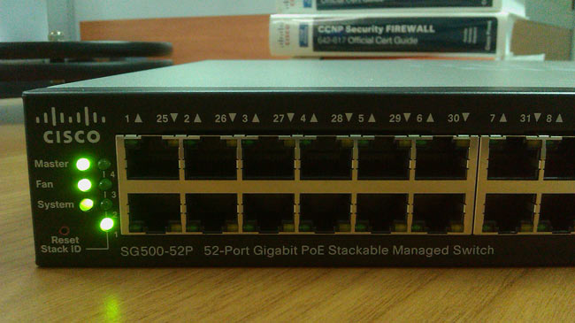
The process of creating VLANs on the SG500 is similar to that of the Catalyst switches. First create your VLANs and then VLAN interfaces to configure IP addresses. Since VLAN 1, the Default VLAN is already created, we only require that we change its IP address to match our network. Keep in mind that the switch has VLAN 1 preconfigured with IP address 192.168.1.254, but also has DHCP enabled, so if the switch finds a DHCP server during startup it will automatically obtain an IP address. When the system uses its default IP address (192.168.1.254), the System LED shown below will flash continuously:
switch# configure terminal
switch(config)# interface vlan 1switch(config-if)# ip address 192.168.1.2 255.255.255.0switch(config-if)# exitWe’ve now set VLAN 1’s IP address to 192.168.1.2. Next step is to create VLAN2 & 5, our Voice VLAN & Guest VLAN, name them and configure an IP address for each:
switch(config)# vlan 2
switch(config)# interface vlan 2
switch(config-if)# name Voice-VLANswitch(config-if)# ip address 192.168.10.2 255.255.255.0switch(config-if)# exitswitch(config)# vlan 5switch(config)# interface vlan 5
switch(config-if)# name Guest-VLAN
switch(config-if)# ip address 192.168.50.2 255.255.255.0switch(config-if)# exitThe vlan 2 & vlan 5 command creates VLAN 2 and VLAN 5, however the switch’s prompt will not change, so do not be alarmed.
Finally, we set the switch’s hostname, configure the default gateway, name-server for dns resolution and enable ip routing:
switch(config)# hostname SG500
SG500 (config)# ip default-gateway 192.168.1.1
SG500 (config)# ip name-server 192.168.1.1SG500 (config)# ip routingSaving Our Configuration
Saving the configuration is easily performed using the classical command:
SG500# copy running-config startup-configOverwrite file [startup-config].... (Y/N)[N] ? Y
02-Feb-2012 10:34:43 %COPY-I-FILECPY: Files Copy - source URL running-config destination URL flash://startup-config
02-Feb-2012 10:34:53 %COPY-N-TRAP: The copy operation was completed successfully
Copy succeededWeb Configuration
For those wishing to use the web interface to configure the switch, don’t despair as there are still plenty of features that can be configured through the web interface. VLAN creation and IP address configuration are certainly a lot faster and easier through the CLI interface, especially if you make a mistake and need to make corrections.
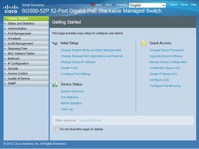
To access the web interface, enter the switch’s VLAN 1 IP address as configured previously. In our example, this is 192.168.1.2. You’ll be greeted with the login screen and prompted to enter a valid username and password. Once entered, the Getting Started screen is shown:
Assigning Ports to VLANs
The web interface provides two different ways to assign VLANs to the switch’s ports. Under the VLAN Management menu, you’ll find thePort-to-VLAN and Port-VLAN-Membership options. The first, Port-to-VLAN option, presents all available ports and by selecting the appropriate VLAN from the top you can assign it, exclude it or make it the native VLAN for any of the selected ports:
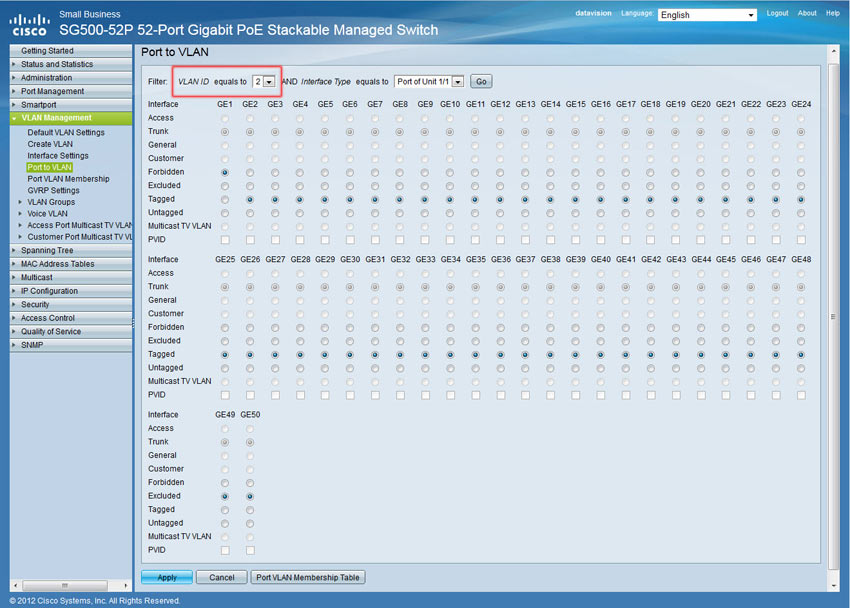
In our example, we’ve selected VLAN 2 (VLAN ID equals 2), our Voice VLAN, and configured all but one port to carry VLAN 2 traffic as Tagged. When configuring a VLAN as Tagged traffic, the port automatically becomes a trunk port and the Trunk option above is greyed out as you cannot disable it – a logical restriction. When configuring a VLAN to Untagged it then becomes the Native VLAN for that port. If these concepts are new, we would highly recommend you read through our VLAN section.
We’ve configured VLAN2 traffic as Tagged, which means we plan to connect an IP Phone to these ports and from there on a PC. VLAN 1 traffic is set as the Untagged traffic, or Native VLAN for all ports.
Finally, Port GE1 is forbidden to carry VLAN2 traffic. The reason for this is that we plan to connect our Internet router on port GE1 and there is no reason for our Voice VLAN traffic to exist on that port, for security reasons of course.
When done, click on Apply to save the changes and continue with the rest of the VLAN port configuration.
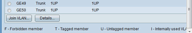
The Port-VLAN-Membership menu provides an overview of all port configuration, however, changes can only be made for one port at a time:
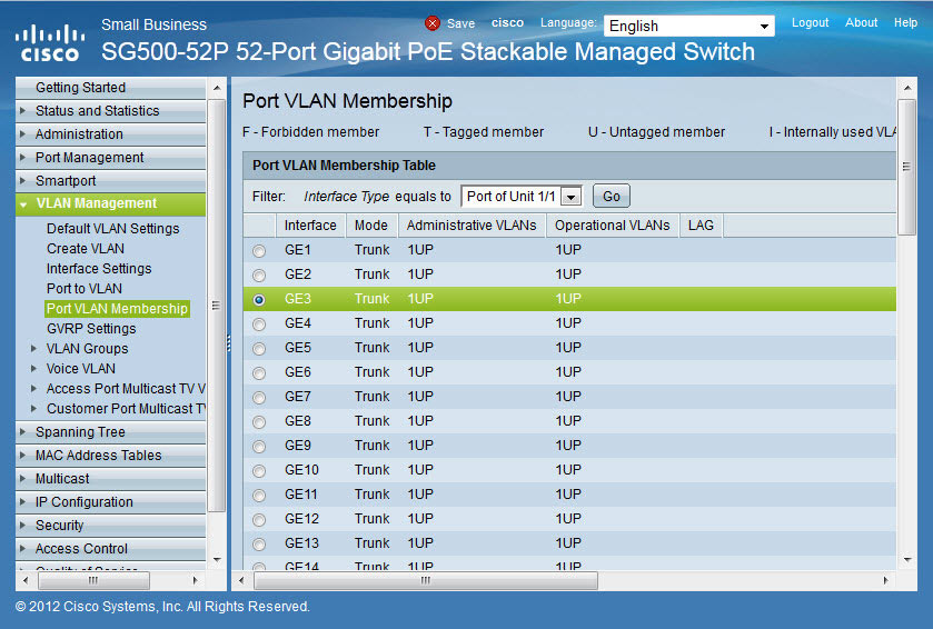
Our screenshot shows no configuration has been made as VLAN2 and 5 are not configured for any port. Select the port of interest and click on Join VLAN at the bottom of the page:
The small pop-up window will appear in which we can select a VLAN from the area on the right (under Select VLAN:), then choose the tagging method for the selected VLAN and finally assign it to the port by clicking on the right arrow ‘>’:
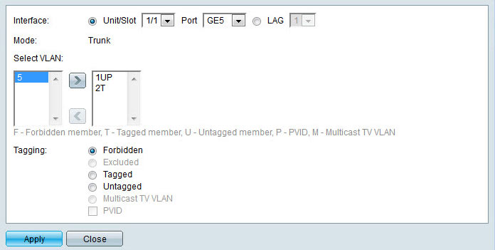
Once complete, click on Apply to save the changes followed by Close to return to the menu, or select the next port to be configured from the upper area of the page.
We should note that the Port-to-VLAN is the fastest way to configure multiple switch ports simultaneously.
Setting System Time
The system’s time can be configured under the Administration > Time Settings > System Time:
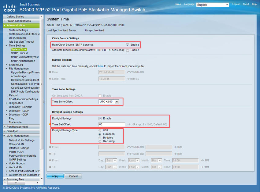
To configure synchronization with an NTP server, enable the Main Clock Source SNTP Servers and set the correct Time Zone Offset. Next, configure the Daylight Saving Settings and click on Apply.
Move to SNTP Unicast menu option, enable the SNTP Client Unicast and add your preferred NTP server as shown below:
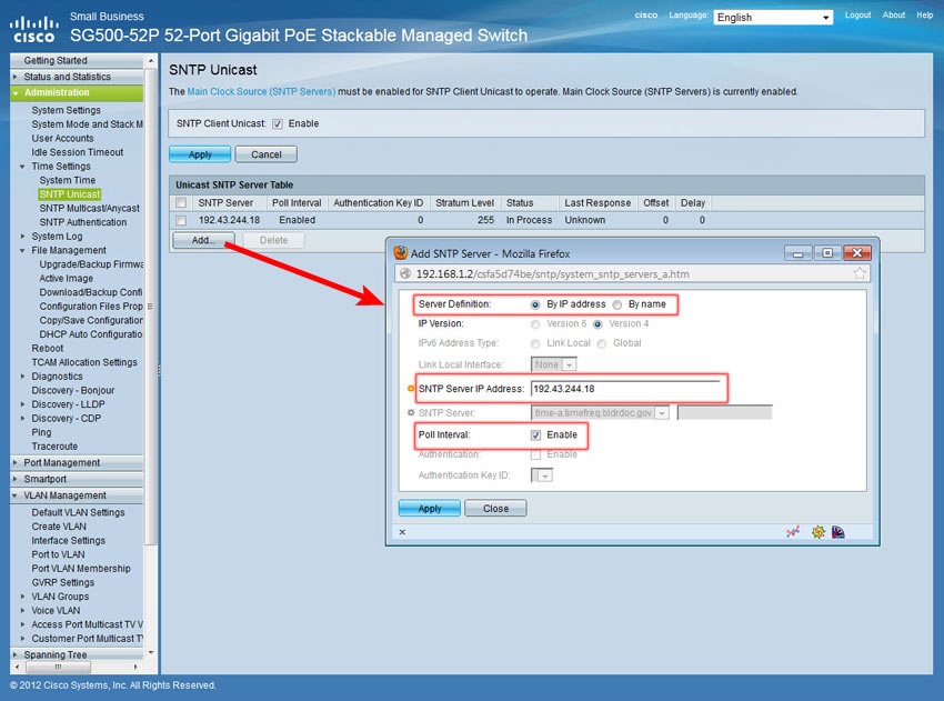
Click on Apply to save your changes.
Creating User Accounts
To create the desired user accounts to access the switch, select the Administration > User Accounts menu.
Currently there is only the default account "cisco". Click on Add and enter the username and password:
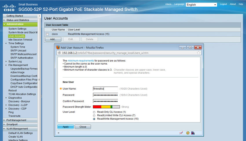
Note the different User Levels available for the user being created. For full access, select level 15.
Once created, the cisco user can be deleted, however it is imperative the configuration is saved by clicking on the flashing Save buttonat the top of the page.
Defining Management Method
Our final step for the basic setup of the switch is to define the management method. The SG500 and previous models support a variety of management methods which include Telnet, SSH, HTTP, HTTPS and SNMP.
To setup your access profile, visit the Security > Mgmt Access Method > Access Profiles:
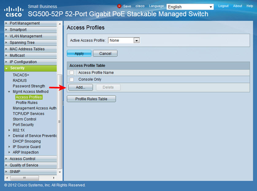
Next, click on the Add button to add a new profile:
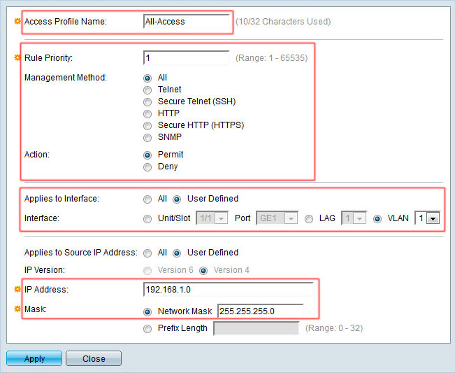
The pop-up window will allow you to define the access profile name, rule priority (the highest rule number takes priority over other access profiles), management method, interface to which it applies and IP Addresses to which access is allowed or denied:
In our example we named our access profile All-Access, set the rule priority to No.1 which takes precedence over other rules, management method of All, permit action, interface VLAN 1 only and source IP of 192.168.1.0 / 24, which of course is the VLAN1 network.
When complete click on Apply and Close.
This action will return you to the Access Profiles section. We now select the Active Access Profile we just created (All-Access) and click on Apply. A pop-up window will request us to confirm this action. Click on OK:
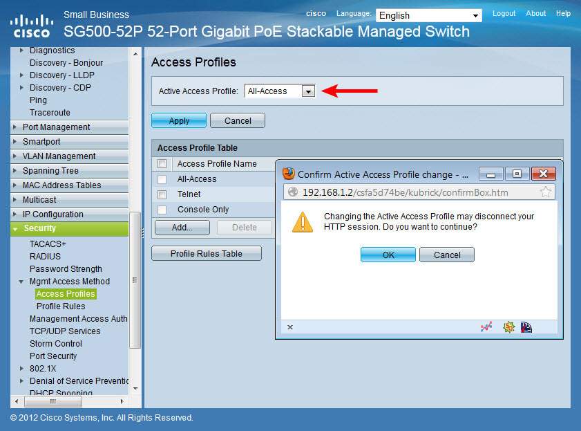
If the session is disconnected, simply reconnect to the switch using VLAN1’s IP address.
Again, do not forget to click on the flashing Save button at the top of the page:
This completes our introduction to the SG500-52p PoE Switch and its basic configuration.
I found this blog after a long time which is really helpful to let understand different approaches. I am going to adopt these new point to my career and thankful for this help.
ReplyDeleteHPE 18 G2 LTO Tape Autoloader