Introduction
So we have covered to some depth the subnetting topic, but there is still much to learn ! We are going to explain here the available subnet masks and analyse a Class C network, using a specific subnet mask. It's all pretty simple, as long as you understand the logic behind it.
Understanding the use, and analysing different subnet masks
Okay, so we know what a subnet mask is, but we haven't spoken (yet) about the different values they take, and the guidelines we need when we use them. That's what we are going to do here !
The truth is that you cannot take any subnet mask you like and apply it to a computer or any other device, because depending on the random subnet mask you choose, it will either create a lot of routing and communication problems, or it won't be accepted at all by the device you're trying to configure.
For this reason we are going to have a look at the various subnet masks so you know exactly what you need to use, and how to use it. Most important, we are going to make sure we understand WHY you need to choose specific subnet masks, depending on your needs. Most people simply use a standard subnet mask without understanding what that does. This is not the case for the visitors to this site.
Let's first have a look at the most common subnet masks and then I'll show you where these numbers come from :)
Common Subnet Masks
In order to keep this place tidy, we are going to see the common Subnet masks for each Class. Looking at each Class's subnet mask is possibly the best and easiest way to learn them.
Numer of bits | Class A | Class B | Class C |
0 (default mask) | 255.0.0.0 (default_mask) | 255.255.0.0 (default_mask) | 255.255.255.0 (default_mask) |
1 | 255.128.0.0 (default +1) | 255.255.128.0 (default+1) | 255.255.255.128 (default+1) |
2 | 255.192.0.0 (default+2) | 255.255.192.0 (default+2) | 255.255.255.192 (default+2) |
3 | 255.224.0.0 (default+3) | 255.255.224.0 (default+3) | 255.255.255.224 (default+3) |
4 | 255.240.0.0 (default+4) | 255.255.240.0 (default+4) | 255.255.255.240 (default+4) |
5 | 255.248.0.0 (default+5) | 255.255.248.0 (default+5) | 255.255.255.248 (default+5) |
6 | 255.252.0.0 (default+6) | 255.255.252.0 (default+6) | 255.255.255.252 (default+6) |
7 | 255.254.0.0 (default+7) | 255.255.254.0 (default+7) | 255.255.255.254 (default+7) * Only 1 Host per subnet |
8 | 255.255.0.0 (default+8) | 255.255.255.0 (default+8) | 255.255.255.255 (default+8) * Reserved for Broadcasts |
The above table might seem confusing at first, but don't despair ! It's simple, really, you just need to look at it in a different way !
The trick to understanding the pattern of the above table is to think of it in the following way: Each Class has its default subnet mask, which I have noted using the Green colour, and all we are doing is borrowing a Bit at a time (starting from 1, all the way to 8) from the Host ID portion of each class. I have used various colours to show you the decimal numbers that we get each time we borrow a bit from the Host ID portion. If you can't understand how these decimal numbers work out, then you should read up on the Binary & IP page.
Each time we borrow a bit from the Host ID, we split the network into a different number of networks. For example, when we borrowed 3 Bits in the Class C network, we ended up partitioning the network into 8 smaller networks. Let's take a look at a detailed example (which we will break into three parts) so we can fully understand all the above.
We are going to do an analysis using the Class C network and 3 Bits which we took from the Host ID. The analysis will take place once we convert our decimal numbers to binary, something that's essential for this type of work. We will see how we get 8 networks from such a configuration and their ranges !
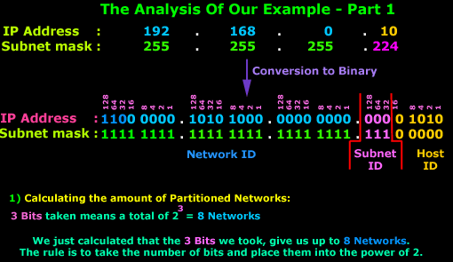
In this first part, we can see clearly where the 8 Networks come from. The rule applies to all types of Subnets, no matter what Class they are. Simply take the Subnet Bits and place them into the power of 2 and you get your Networks.
Now, that was the easy part. The second part is slightly more complicated and I need you focused so you don't get mixed up!
At first the diagram below seems quite complex, so try to follow me as we go through it:
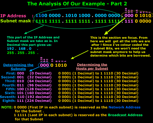
The IP Address and Subnet mask is show in Binary format. We focus on the last octec which contains all the information we are after. Now, the last octec has 2 parts, the Subnet ID and Host ID. When we want to calculate the Subnets and Hosts, we deal with them one at a time. Once that's done, we put the Subnet ID and Host ID portion together so we can get the last octec's decimal number.
We know we have 8 networks (or subnets) and, by simply counting or incrementing our binary value by one each time, we get to see all the networks available. So we start off with 000 and finish at 111. On the right hand side I have also put the equivalent decimal number for each network.
Next we take the Host ID portion, where the first available host is 0 0001 (1 in Decimal), because the 0 0000 (0 in Decimal) value is reserved as it is the Network Address (see IP Classes page), and the last value which is 1 1111 (31 in decimal) is used as a Broadcast Address for each Subnet (see Broadcast page).
Note
I've given a formula in the IP Classes page that allows you to calculate the available hosts, that's exactly what we are doing here for each subnet. This formula is :2 to the power of X -2. Where X is the number of Bits we have in the Host ID field, which for our example is 5. When we apply this formula, we get 2 to the power of 5 - 2 = 30 Valid (usable) IP Addresess. If you're wondering why we subtract 2, it's because one is used for the Network Address of that subnet and the other for the Broadcast Address of that subnet. This shouldn't be new news to anyone :)
Summing up, these are the ranges for each subnet in our new network:
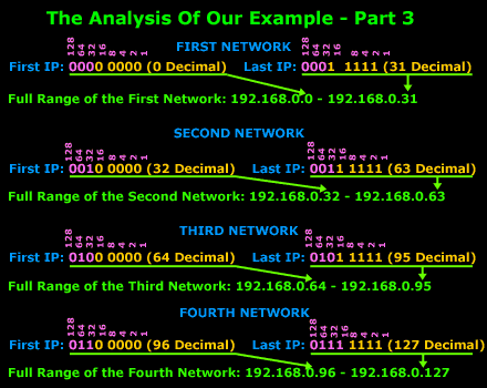
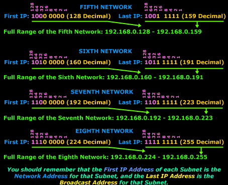
I hope the example didn't confuse you too much; the above example is one of the simplest type, which is why I chose a Class C network, they are the easiest to work with.
If you did find it somewhat difficult, try to read over it slowly. After a few times, you will get to understand it. These things do need time to sink in !
| Subnet Routing & Communications |
Introduction
Routing and Communication between subnets is the main topic here. This article analyses communications between subnets. We provide examples on different methods that can be used to enable subnet communications in an effective and secure manner. Generally, this article puts in practice all subnetting theory covered until now.
Communication Between Subnets
So, after reading all the previous pages about subnetting, let me ask you the following:
Do you think computers that are on the same physical network but configured to be on separate subnets are able to communicate ?
The answer is "no". Why ? Simply because you must keep in mind that we are talking about the communication between 2 different networks !
Looking at our example of the Class C network on the previous page, the fact is that one computer is part of the network 192.168.0.0 and the other one part of network 192.168.0.32, and these are two different networks. In our example, from the moment we modified the default subnet mask from 255.255.255.0 to 255.255.255.224, we split that one network to 8 smaller ones.
Let's try it !
And because we just have to prove it..... we are going to try it on my home network ! In the worst case I'll have to spend all night trying to figure out what went wrong but it will be worth it ! :)
Without complicating things, here is a diagram of my home network (I've excluded any computers we are not going to be using, in order to save space):
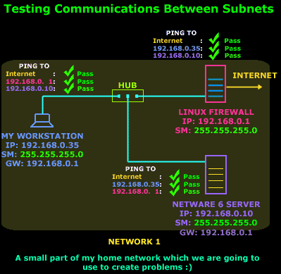
Well, that's the network we have to play with. I have put on the diagram the results of a few simple pings from each host and as you can see, they all came out nice: PASS.
So in order to proceed to phase 2 of our experiment, I modified the Subnet mask of my workstation to 192.168.0.35 / 255.255.255.224 , my Slackware Linux Firewall to 192.168.0.1 / 255.255.255.224 (internal Network Interface Card) and my NetWare 6 Server to 192.168.0.10 / 255.255.255.224 as shown in the diagram below:
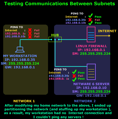
As you can see, the results for my workstation were devastating ... alone and totaly unaware that the other two servers are still there ! When my workstation tries to actually ping the Linux Firewall, it will get no reply, because its Gateway is a host which belongs to another network, something that we knew would never work.
So, we have concluded that there cannot be any sort of communication between the computers of Network 1 and Network 2.
So how can two hosts in two different subnets talk to each other ? That's what we are going to have a look at right now !
Building The Bridge
There is a way to allow the communication between my workstation and my servers and the Internet. Actually there are a few ways to achieve this and I'm going to show you a few ways, even though some might seem silly or impractical. We are not interested in the best solution at the moment, we just want to know the ways in which we can establish communication between the two subnets.
Considering that subnets are smaller networks, you would remember that we use routers to achieve communications between two networks. This example of my home network is no exception to this rule.
We need a router which will route packets from one network to the other. Let's have a look at the different ways we can solve this problem:
Method 1: Using a Server with 2 Network Cards
Our first option is to use one of the Servers, or a new Server which has at least 2 network cards installed. By connecting each network card to one of our networks and configuring the network cards so that each one belongs to one subnet/network we can route packets between them:
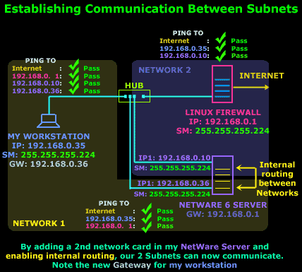
The above diagram shows pretty much everything that's needed. The 2nd network card has been installed and it's been assigned an IP Address that falls within our Network 1 range and therefore can communicate with my workstation . On the other hand the NetWare server now acts as a Gateway for Network 1, so my workstation is reconfigured to use it as its Gateway. Any packets from Network 1 to Network 2 or the Internet will pass through the NetWare server
Method 2: Binding 2 IP Addresses to the same network card
This method is possibly the best and easiest way around our problem. We use the same network card on the NetWare server and bind another IP Address to it.
This second IP Address will obviously fall within the Network 1 IP range so that my workstation can communicate with the server:
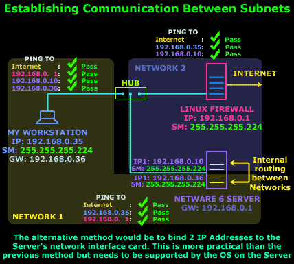
As noted on the diagram, the only problem we might encounter is the need for the operating system of the server to support this type of configuration, but most modern operating systems would comply.
Once configured, the Server takes care of any routing between the two networks.
Method 3: Installing a router
The third method is to install a router in the network.
This might seem a bit far fetched but remember that we are looking at all possible ways to establish communications between our networks ! If this was a large network, then a router could possibly be the ideal solution, but given the size of my network, well... let's just say it would be a silly idea :)
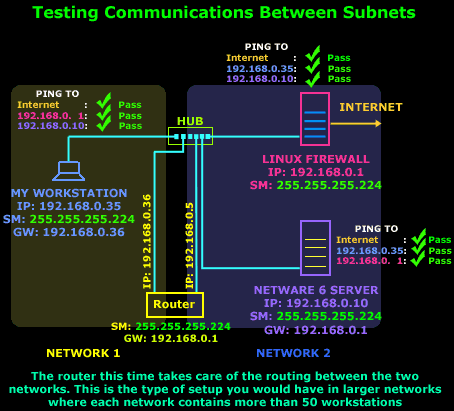
My workstation in this setup would forward all packets to its Gateway, which is the router's interface and is connected to Network 1 and it will be able to see all other servers and access the Internet. It's a similar setup to Method 1 but instead of a Server we have a dedicated router. Oh, and by the way, if we would end up using such a configuration in real life.. the hub which both of the router's interface's connect to, would be replaced by some type of WAN link.
That completes our discussion on Subnet routing and communication.
No comments:
Post a Comment